

PRINCIPLES OF OPERATION
Technology
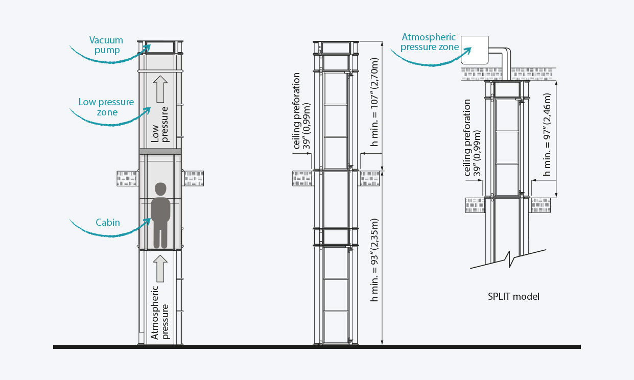
The vacuum elevator combines a smooth vertical cylinder with a coaxial car that moves up and down through air suction. The principle operation of the elevator is based on the ascending push generated by the difference between the atmospheric pressure on the top of the car and the atmospheric pressure under the car.
The depression (vacuum) required to lift the car is achieved by turbines operating as exhaust fans, located at the top of the elevator.
The piston gear surrounded by a sliding air-tight seal allows an almost frictionless movement and hoists the car due to the pneumatic depression generated on the upper part.
A valve regulating inflow of air controls the pneumatic depression, enables descent and controls the speed of the car.
The lower part of the shaft is open to ensure free entrance of air at atmospheric pressure.
At each floor or level, perimeter seals on the door are self-sealing due to the action of the atmospheric pressure.
The car has locking devices to stop at the upper and lower limits of travel.
A safe braking device (chute) activates in case of free fall.
THREE MAIN PARTS OF
Elevator
EXTERIOR CYLINDER
The cylinder is a transparent self-supporting tube, built around a specially designed aluminium structure. The tube walls are made of curved polycarbonate sheets. The tube consists of modular sections, which can be easily fitted together. The roof of the tube, made of steel, ensures air-tight closures with suction valves and inlets.

ELEVATOR CAR
The car runs inside the cylinder on rails or columns, which are part of the same self-supporting structure of the cylinder. The walls of the car are made of transparent poly-carbonate panels. The car is also equipped with an anchoring system that activates on reaching the indicated floor, provides precise but smooth stops, and locks the car mechanically.

SUCTION ASSEMBLY
The suction assembly or “Head Unit” is on the top of the cylinder, where the turbines, the valves and the controls are located. The control cabinet is a metal box housing with a PVE controller board and other electrical devices. The head unit is built and placed on either the same tube that holds the car (standard), or separately (split unit) at distances of up to 30 linear feet (10m) from the lift. The frame of the suction assembly is made of either fibre glass or steel depending upon the model.

WATCH HOW THE